For frequency stabilization of VFO //éeékéküiFrequency Lock Loop) & LED 2digits frequency display
- Although PLL for VFO frequency stabilization using 74LS93(prescaler 1/8 )+4013 (D-FF)+CA3140 (OPamp) was announced by CQ magazine October, 1983 issue P405-/JA2D RF --
ü×Just look--, This time is the PIC version of that.
-The software of this PIC version is a frequency counter fundamentally, it can display the frequency with IF offset
-They are 2 digits of 1kHz, and 0.1kHz.
Since there is probably a scale in the knob of the home-brew VFO or VXO, the level of 10kHz can be read. Therefore, inconvenience will not be felt if 1kHz or less is displayed.
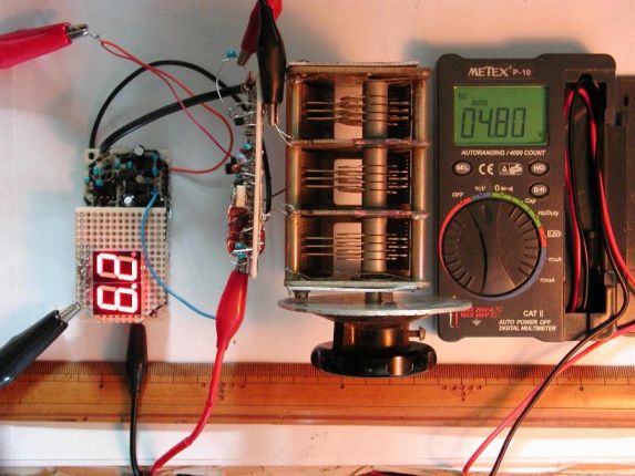
- Left-hand side; under the test of VFO of 7MHzCW transceiver (IF=10.17MHz) of a future manufacture schedule. 17,106.2kHz oscillation. The display of FC counter is 6.2kHz. A blue wiring is the feedback voltage (4.8V) to variable capacitance of VFO.
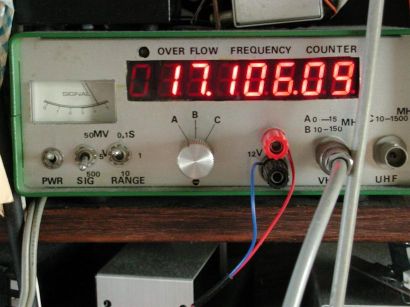
-and a center; the signal is supervised at the frequency counter. 17,106.09kHz.
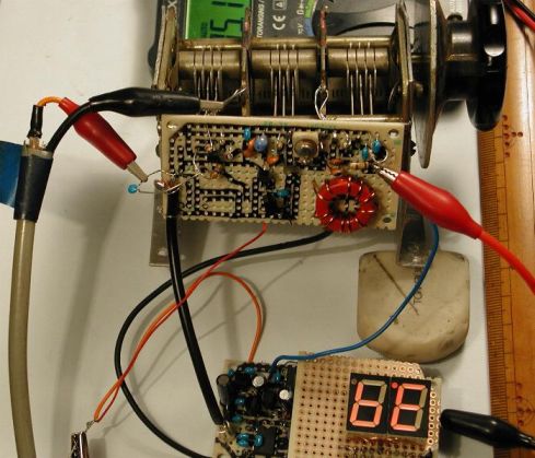
-Right-hand side; -- Amidon core T68-#2 (red) VFO. Although I feel a long time ago that it was good to a slight degree for the stability of VFO, unless it uses as the coil of a tight bobbin whether for the arm to have become blunt, doesn't stability go up? It moves well by the self-drift. Hi
Result of actual test
Drift without FLL 15üF50üi17,107.70kHz)ü©ü@16:05(17,107.56kHz)ü@//ü@140Hz/15Ģ¬
ü@
Drift with FLLü@15üF35üi17,107.09kHz) ü© 15:50(17,107.10kHz)ü@//ü@10Hz/15Ģ¬
Drift with FLL 16:05(17,107.06kHz)ü©17:05(17,106.99kHz)ü©19:05(17,107.23kHz)ü@//170Hz/3hours
Circuit
TD7104P(prescalerüĆ8üAüĆ1üj+2SC1906 pre-amp and PIC16F84A-P20 counter, driving 2digits of 7segment LED.
- Although prescaler TD7104P(1/8) is used, since it can count-up to 35MHz or more with a PIC itself, TD7104P is unnecessary in the handmade VFO of 20MHz or less.
- In case of Rb.1 grounded by 2.4kohm, since it multiplies by 1 inside the PIC, it will be in the state where there is no prescaler.
- The prescaler TD7104P is used only in the case thatü@VXO drift is large--for higher frequency rig like 144MHz TRX-- .
Notes for brewing
- VFO is mechanically solid and it is a major premise that the drift characteristic is good. Unstable VFO never is not stabilized.
- If the drift of VFO is not 40Hz or less in 2 seconds, a frequency will be unlocked theoretically. Moreover, the drifting direction must be one way. It does not go well in VFO with +/- drifting.
- According to the VFO characteristic, Try & Adjust is required for R (47Mohm) of the integration circuit of OP-amp CA3140, and 2.2 micro F.
Algorithm of PIC-FLL
- There may be the room of still more an improvement, but has been uploaded to web..
-1-- A frequency count is carried out with gate time=1.0sec. It is put into register vfo[3]-vfo[0]// 32 bits.
-2-- Hexadecimal of vfo[3]-vfo[0] is converted to decimal number and the figure of 1kHz, and the 0.1kHz is put into dsp[1] and dsp[0].
-3-- The frequency measured 1 second before(last time) was in the oldv[3]-oldv [0], and subtracted like "X=vfo-oldv".
-4-- It judges that the dial knob was manually turned greatly when it was "X>5000Hz", and it measures the voltage Vp of the output pin 6 of OP-amp CA3140 by PIC-porta.2 and if it is "4 V
- Since the threshold of the each input port of PIC is 1.25V without hysteresis, the voltage detection can be carrying out by ON/OFF of 2SC1815 using this.
-5-- If it is "X<5000Hz", after comparing the value of 0-255 of vfo [0] and the lock frequency of the 42, 127, and 213 Hz, PIC-porta.1 is set to H or L and the voltage Vp of the output pin 6 of OP-ampCA3140 is adjusted so that it may fall in the nearest value of 42, 127, and 213 Hz.
That is, it locks at intervals of 85Hz.
For example, if it is, vfo[0]=180, since 213Hz is the nearest, PIC-porta.1 is set to L and voltage Vp is pushed up.
-6-- Above operation is conducted, the value of oldv[3-0] is replaced with the value of the newest vfo[3-0], and returns to the first -1--.
---In addition to the above,
Since the chirping of the CW tone was worrisome during the frequency automatic adjustment, the program was changed so that the ON/OFF time is proportional to the difference of drifts.
If a deviation is 25Hz, 62.5%=[(25*4)/160] of the 1 second are turned ON, and the remainder is turned OFF(tristate of PIC-RA1 port).
--- deviation if it is 3Hz -- 7.5%=[(3*4)/160] is ON, the remainder is OFF.
PCB
 üEThe above is 2digits LED. The lower of it is FLL. Both are connected with 14p-connector.
The size of the FLL is 72mmWx36mmH x25mmdepth.
üEAt the lower left, you can see the tact-SW for IF offset.
Program software and pattern of PCB
Program is downloaded bellow.
ü@ü×downloaded Fll2.asm & Fll2.hex /Self-defrosting software.EXE
Pattern of PCB, Fll.pcb is required for the application of PCBE software.
ü×PCBE D/L
ü@ü×"Fll.pcbe" Pattern of PCB /Self-defrosting software.EXE(52kB)
Expalnation of PIC function
Normal frequency counter starts in case of power-on with RB7=H(open)üARB5=HüARB6=H. Then the carrier frequency of the SSB generator is displayed and depress the RB7-tact SW, then IF is saved in the EEPROM and displaying ó7.3üv.
After that, please power off. Then set RB5 and RB6 as you intend the heterodyne type for IF offset.
IF offset revision after assembled in the rigüHüH
(In case of other than RB5=RB6=H üj
The depressing knob for the RB.7 tact SW is required from the front panel.
If you want to set IF=10,123.5kHz,
1)Depress the RB7 tact SW, it changes the normal freuncy counter and blinking on the digit of 1kHz.
2)Tune the Lo so that LED displays the [3.5kHz].
3)Depress the RB7 tact SW once again, LED will displays the [7.3] and IF offset is saved on the EEPROM.
4)Power OFF and power ON, then LED is displayed with IF offset=xx,xx3.5kHz.
Example of RIG where FLL is appllied
This is the Web site of Japanese language, but you can understand the block diagram and the wiring circuit.
7MHz CW QRPp transciever