Frequency Counter
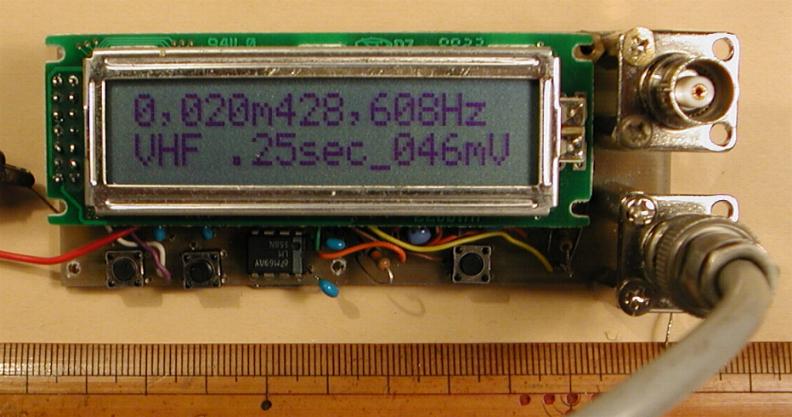
*This is the Frequency Counter for 100Hz-2.5GHz, using LCD 16 chara.x 2 lines ,TCXO 12.8MHz(1ppm ) and PIC16F84.
*The Voltage(0-510mV) of the input signal is also indicated on the LCD , therefore tuning of the coil can be conducted while checking the frequency.
*Furnished with IF offset-function, this can be applied for the frequncr display of the home brewed transeiver.
*Print circuit board size is very small of 100mm x 43mm.
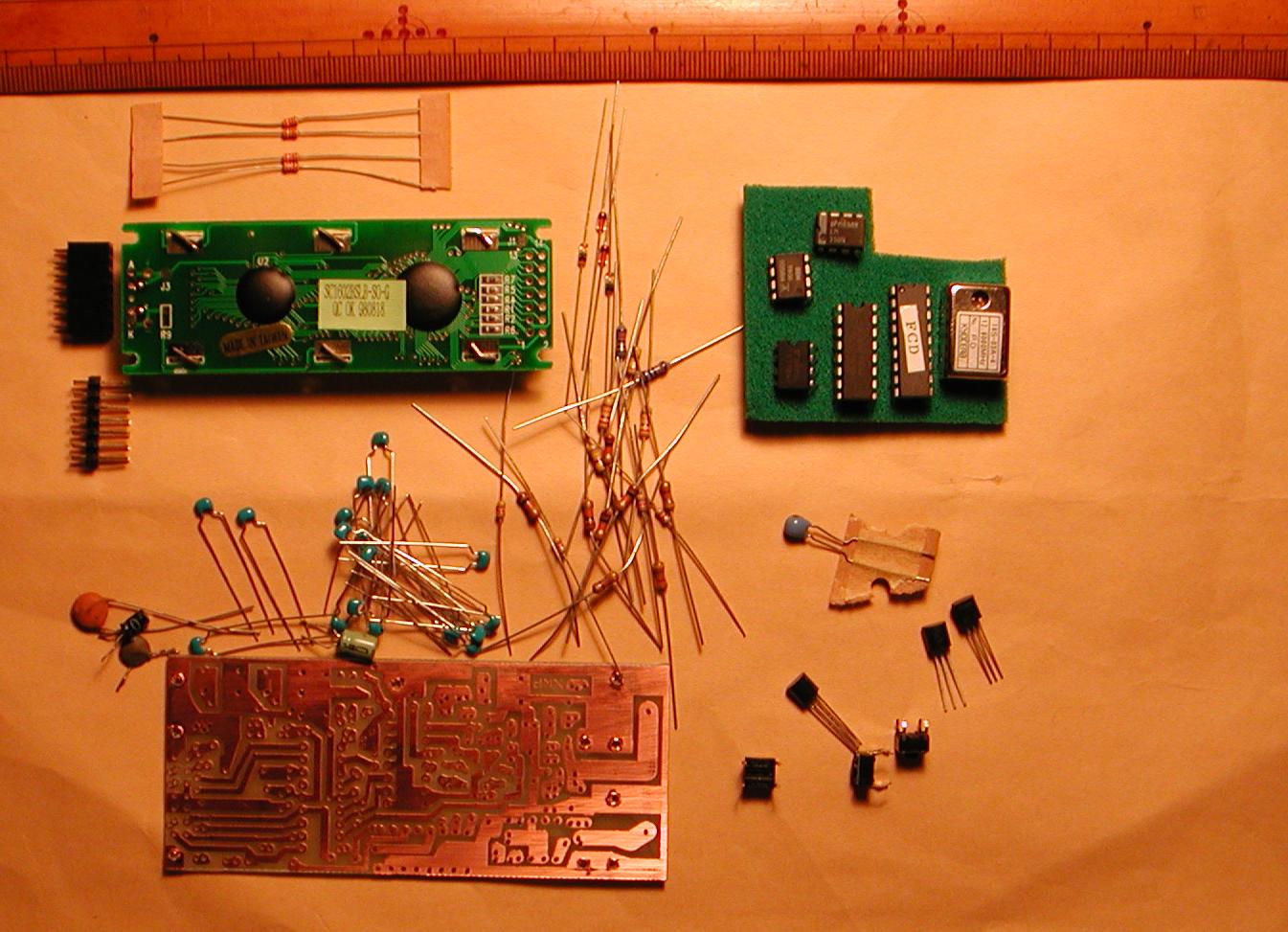
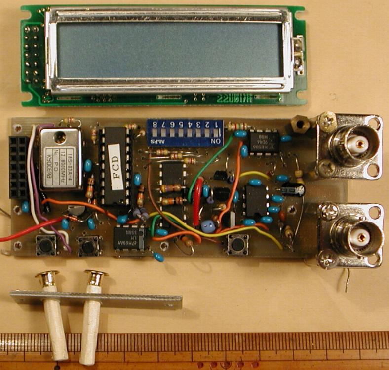
*All of the parts are shown. LCD is easily disconnected by using the 20 pin connector which is attached with LCD at AKIZUKI shop.
*BNCs for RF signal input are also soldered directly on the PCB and all of the part are assembled to one body.
Specification
| Input port | frequency(Hz) | pre-amp | Gate time(sec) | note |
|
| RF | 100--30M | 2SK241+2SC1815 | 0.25, 1.0, 10 | RF, HF, VHF same BNC port |
| HF | 1M--38M | TD7104P(1/1) | 0.25, 1.0, 10 | ditto |
| VHF | 10M--280M | TD7104P(1/8) | 0.25, 1.0, 8 | ditto |
| UGF | 30M--2.5G | MB506(1/64) | 0.32, 1.0, 6.4 | ditto BNC port |
Program source and Print circuit board
Ideas for program source is refered to the previouse HP Japanese"LED frequency counter "
download Program source FCD5.asm & FCD5.hex for Circuit-full option, simple1 and simple2 //Compression.zip
Aplication softwear PCBE for *.pcb can be downloaded from the
PCBE soft wear download site
Pattern PCB ;"FCD.pcbe" //self-decompression.EXE(110kB)
BPM image for PCB pattern (1100kB)
Manual for Function
*HOW TO IF OFFSET
When the power turned on with RB3=H(open), RB5=H, and RB0=H, it is normal frequency counter. While the carrier frequency of the SSB generater is measured, once the tact SW for RB7 is pushed, LCD shows "ADJ", twice the tact SW for RB7 is pushed, LCD shows "OFF".
*After the power is turned off, then RB5 and RB0 are set H/L as required Hetrodyne, you can make the display figure with IF offset.
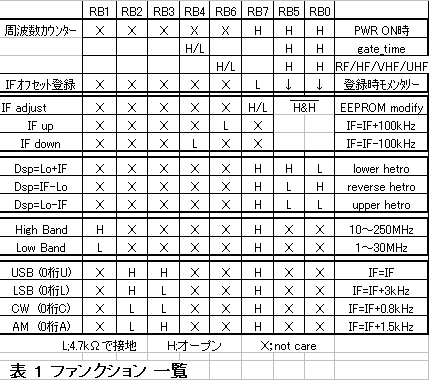
How to do when the IF data of the EEPROM is lost at ON/OFF??
*Three holes are provided on the front panel of the transeiver so that three tact SWs can be on/off from outside. For example, IF is assumed on 10,120kHz.
1. Normal counter after RB7-SW on.
2. By adjusting the LoüAfigures below the 10kHz should be tuned like "xxx,x20kHz" .
3. Push the RB7-SW,LCD displays "AJD".
4. Push the RB4-SW, Frequency shifted -100kHzüB
5. Push the RB6-SW, Frequency shifted +100kHzüB
6. Push the RB7-SW, LCD displays "OFF" and IF data is saved on EEPROM.
7. Reset the power.